Get a Quote
98% Accuracy 24-48h Turnaround 8+ Years Experience

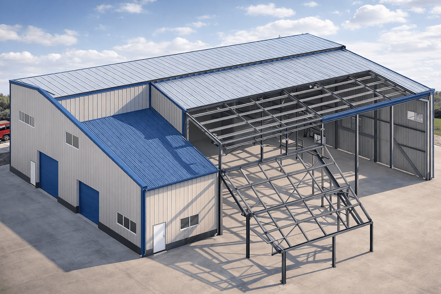
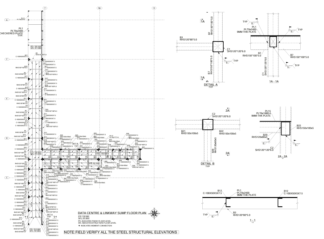
Precision Steel Detailing & Estimation Services

Flexi Steel Structures provides professional structural steel detailing, miscellaneous steel detailing, material takeoff, and connection engineering for fabricators and contractors across the United States, Canada, UK, and AU/NZ.
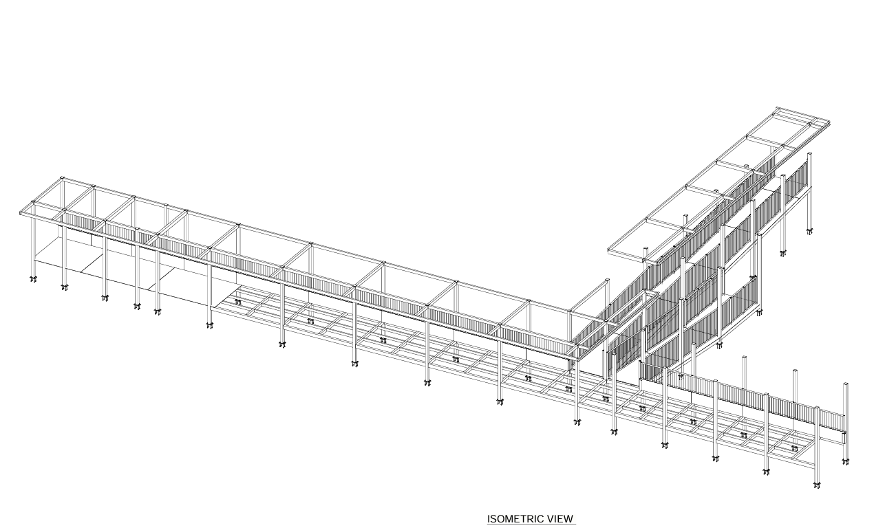
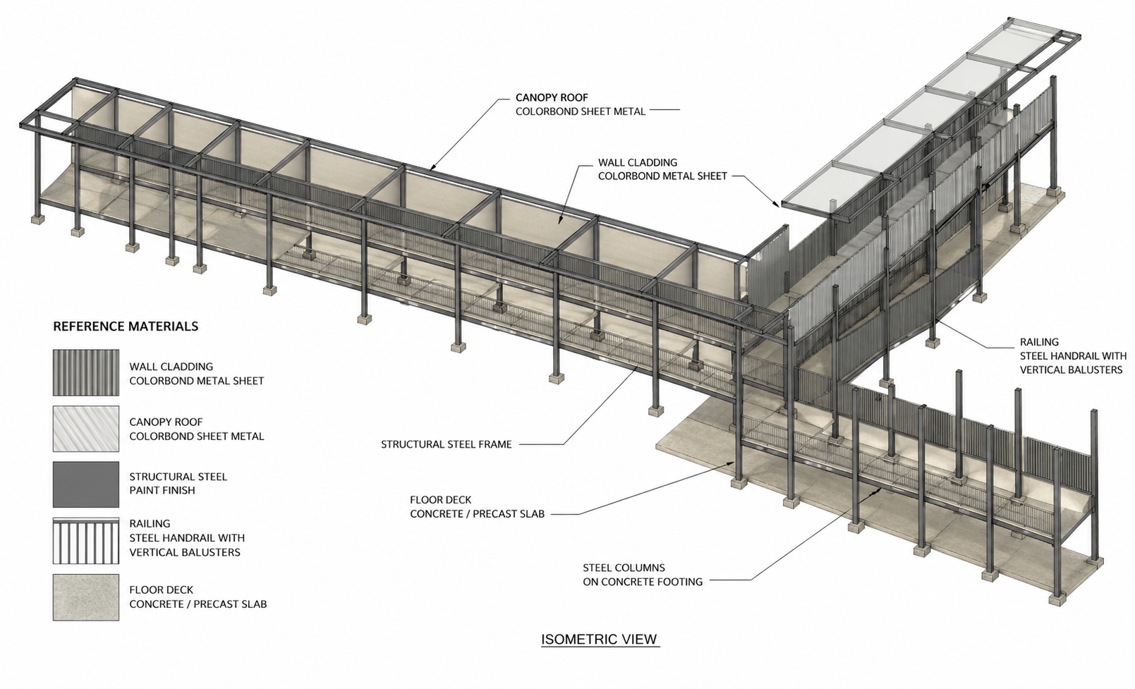
BIM Modeling

3D coordination | Clash detection | Accurate material lists

3D BIM model of structural steel frame

Trusted by fabricators & contractors across

United States Canada United Kingdom Australia & New Zealand
2022
Year Established
180+
Detailing Projects
360+
Material Takeoffs
540+
Projects Completed
What We Do

Comprehensive Steel Detailing Services

Delivering precision and reliability for every project

Structural Steel Detailing

Complete shop and erection drawings for schools, office buildings, industrial facilities, retail, and more.

  • Schools & Educational
  • Office Buildings
  • Industrial Facilities
  • Retail & Commercial

Miscellaneous Steel Detailing

Detailed drawings for monumental stairs, switch back stairs, stair towers, curved stairs, rails, ladders, and more.

  • Monumental Stairs
  • Stair Towers
  • Railings & Ladders
  • Curved Stairs

Material Takeoff Services

Accurate quantity extraction using advanced BIM modeling for precise material pricing and procurement.

  • 3D Model Generation
  • Real-world Connections
  • Cost Analysis
  • Accurate Estimates

Connection Engineering

Licensed professional engineers to design connections and review projects detailed by our team.

  • Licensed Engineers
  • Full Calculations
  • Nationwide Coverage
  • Code-Compliant Design
Workflow

Steel Detailing Process — Step-by-Step

Every project follows a structured workflow with QA/QC checkpoints at each stage.

01

Project Intake & Scope Review

Receive IFC/PDF drawings. Define scope, connection types, applicable codes (AISC, CISC, ASI, BS & EURO CODE). Assign lead engineer and confirm timeline.

02

3D BIM Modeling

Build accurate 3D model covering all members, connections, welds, bolts, and embeds per structural engineer's specifications.

03

IFA Drawing Production

Generate Shop & Erection drawings for Issued For Approval submission. Senior engineer QA review completed before delivery.

04

Client Review & RFI Resolution

Client marks up drawings. All RFIs resolved within agreed turnaround. Client approval gate before proceeding to IFC.

05

IFC / Final Submission

Issued For Construction drawings + NC/DXF files + Anchor Bolt Plans + Part Lists + BOMs delivered in agreed formats.

06

Post-Delivery Support

Field queries, change orders, and EOR coordination handled promptly through the entire fabrication phase.

Estimodeling Workflow

Material Takeoff Process — Estimodeling Workflow

From your drawings to bid-ready quantity reports — in as little as 8 hours.

01

Step 1 — Receive Drawings

Share IFC, PDF, or Excel files via email or file transfer. We accept DWG, Revit, BIM models, or paper drawings.

PDFDWGDXFIFCExcel
02

Step 2 — Build 3D Estimodel

Our certified team models your project in BIM software in Estimodeling mode for maximum member-wise accuracy.

Full 3D ModelMember-wise
03

Step 3 — Extract Quantities

Member-wise material reports extracted automatically. Hardware, bolt counts, and stock lengths are all included.

Material ReportsHardware Count
04

Step 4 — QA Review

Senior engineer cross-checks all quantities against the original drawings. Markup PDFs generated for full traceability.

Senior EngineerMarkup PDFs
05

Step 5 — Deliver Reports

Excel, CSV, or custom format delivered in 8–48 hours. Ready to import directly into PowerFab or your preferred estimating platform.

Excel FormatCSV FormatPowerFab Ready
Typical Turnaround: 8–48 Hours
Expedited options available for urgent projects
Request Accurate Takeoff Quote

98% accuracy guaranteed | Free quote within 12 hours

Quality Assurance

QC Process — 4-Stage Quality Control

Every deliverable passes through multiple QA/QC gates before client submission.

01

QA Stage 1 — Model Integrity Check

All member sizes verified against EOR drawings. Connection geometry and bolt spacing checked. Full 3D clash detection run on the model.

02

QA Stage 2 — Drawing Review

Cross-reference all dimensions against the model. Verify weld symbols, material callouts, and NISD, AISC, CISC, ASI, BS & EURO CODE annotation compliance throughout.

03

QA Stage 3 — Quantity Verification

Member count verified against drawing schedule. Hardware and bolt quantities cross-checked. Stock lengths confirmed against procurement requirements.

04

QA Stage 4 — Senior Engineer Sign-Off

Final review by engineer with 8+ years' experience. All RFIs cleared before delivery. Version-controlled file delivery with complete revision log.

100% QC compliant deliverables
Every drawing & report reviewed through all 4 stages

Sample Projects

Recent work from across North America

About FSS

Flexi Steel Structures

Founded in 2022 | Coimbatore, Tamil Nadu, India

The FSS team is committed to providing reliable, consistent, quality detailing. Through our knowledge, expertise, and commitment to quality, we ensure each project is completed to each client's expectation.

AISC, NISD CISC, ASI, BS & EURO CODE
BIM Modeling Experts
US, CA, UK, AU/NZ Served

Headquarters

Coimbatore, Tamil Nadu, India


+971 523504532

sales@flexisteelstructures.com

What Our Clients Say

Trusted by fabricators and contractors nationwide

"FSS's attention to detail is unmatched. Their shop drawings required zero redlines - that never happens in this industry. Will definitely use them again."

Sarah K.
Steel Fabricator, Ohio

"Their material takeoff service saved us over $12,000 on a school project. The accuracy of their quantity reports is incredible."

Mike R.
Project Manager, Texas

Frequently Asked Questions

Yes. All drawings are developed from IFC/approved design drawings and coordinated with architectural and MEP inputs. We run clash checks before issuing. Any ambiguity is raised as RFI before release.

Absolutely. All dimensions, levels, and orientations are clearly defined. No "by site" or missing values. Critical dimensions are double-checked, and general notes clarify any tolerances.

Yes. Every connection includes bolt diameter, grade (e.g., 8.8/10.9), hole type, and tightening requirement. Weld sizes, types, and symbols follow IS 800 or project-specific codes.

BOM is extracted directly from the 3D model, ensuring consistency with drawings. We run quantity checks and revision comparisons to eliminate mismatches.

We optimize wherever possible—standard plate sizes, minimal weld complexity, and practical cut lengths. However, we never compromise structural intent. Any optimization is discussed and approved.

Revisions are clearly clouded and tracked with revision numbers. We provide a revision summary and highlight affected parts only, so you don't have to recheck the entire drawing set.

Yes. CNC files are generated from the model and verified for compatibility. We ensure they align with machine requirements and match the latest revision drawings.

Yes. Member lengths are split based on transport limits and site handling capacity. Erection drawings include sequence, orientation, and match-marking for easy assembly.

Standard fabrication tolerances are followed per AISC or project specs. Critical fit-up areas (like base plates, splices) are dimensioned precisely to avoid site issues.

We maintain quick turnaround on RFIs—typically within 24 hours. Urgent shop queries are prioritized to avoid production delays, with direct coordination via email or call.

Request a Quote

Send us your project details and we'll respond within 12 hours.

You can upload multiple files
Secure upload | 12-hour response | NDA available

Get In Touch

Headquarters

Coimbatore, Tamil Nadu, India


Certifications

AISCNISDAWS